[DSP] W05 - Ideal Filters
contents
- frequency classification
- ideal low pass filter
- derived ideal filters
- demodulation - frequency domain
- based on the frequencies that filters attenuate or boost, they maybe classified into different categories
- low pass filter:
- lets through only low frequencies
- kills high frequencies
- high pass filter:
- reverse operation of low pass filter
- bandpass filter:
- allow a middle band
- kills low end and high end
- ideal filers:
- theoretical best performance filters in each class of filters
- similar to an ideal engine
- cannot be implemented in real life
- a useful paradigm to understand limitations of real-world filters
frequency classification
- based on the shape of magnitude response of filters, they can be categorized into four types
- lowpass
- let low frequencies live and kill everything else
- highpass
- let high frequencies live and kill the rest
- bandpass
- let a band of central frequencies through and kill all else
- allpass
- let all frequencies through
- the magnitude curve is a constant through all frequencies
- lowpass
- this mirrors the time-domain filter classification
-
moving-average and leaky-integrator are lowpass filters
- filters can also be classified based on phase change characteristic
- linear phase
- non-linear phase
ideal low pass filter
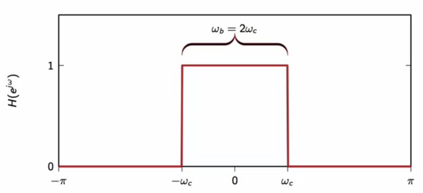
fig: ideal lowpass filter magnitude spectrum
- : cutoff frequency
- frequencies above are killed
- below it are let through filter
- the magnitude response transistions from to at
- filter bandwidth:
ideally:
- lowpass filters are those which let all low band frequencies through
- low frequency signals are untouched
- completely attenuates high frequencies
- magnitude of spectrum is
- for the low frequency pass band
- for the high frequency stop band
- for this, magnitude response should be a real function
- zero phase filter
- no delay is added by the filter
formal low pass filter
- perfectly flat passband
- infinite attenuation in the stopband
- zero-phase (no-delay)
impulse response of ideal lowpass filter
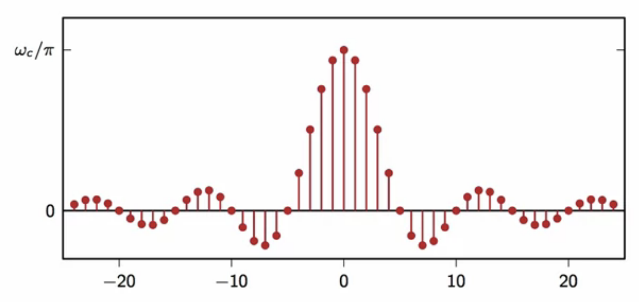
fig: ideal lowpass filter impulse response
- response has a nice oscillatory shape
- response is an infinite support impulse response
- infinite both to the right and left
- no matter how the convolution is computed, there will always be an infinite number of operations to compute
- this is the ideal behavior and causes issue in real world filter implementation
- cannot compute the output in a finite amount of time
- this behavior is approximated to build filters that respond in finite time
- approximation for computable, usable, real-world filters
- the impulse response decays very slowly over time; i.e. @ rate
- a lot of samples are needed for a good approximation
dedicated filter response functions
- the sinc-rect pair:
frequency response of lowpass filter
- frequency response in terms of a function of ideal lowpass filter is
- : cutoff frequency of lowpass filter
impulse response of lowpass filter
- impulse response in terms of a function of ideal lowpass filter is
relationship between lowpass filter impulse and frequency response
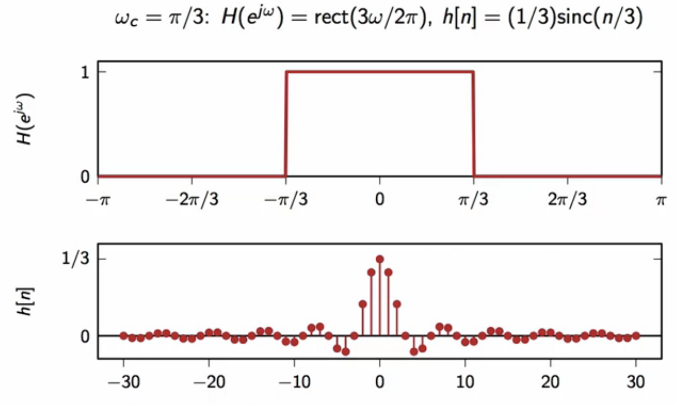
fig: ideal lowpass filter frequency (top) and impulse response (bottom) relationship
- here:
quirks of the ideal lowpass filter
- the function is not absolutely summable
- consequently, the ideal lowpass is not BIBO stable
- example:
-
consider a bounded input signal for ideal filter
- to compute output of ideal filter, convolve this input and impulse response of ideal lowpass filter
- the convolution is divergent computation
-
however, the divergence is fairly slow
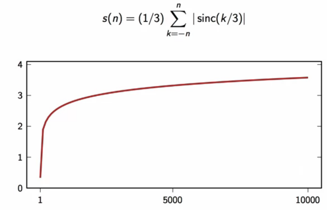
fig: slow divergence of the ideal lowpass filter convolution with input
derived ideal filters
- a series of other ideal filters can be derived from the ideal lowpass filter
ideal highpass filter
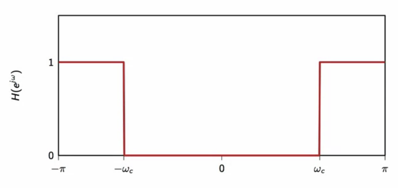
fig: ideal highpass filter magnitude spectrum
formal ideal highpass filter
- it can be seen that the ideal highpass is a complementary filter of an ideal lowpass filter in the frequency domain
ideal bandpass filter
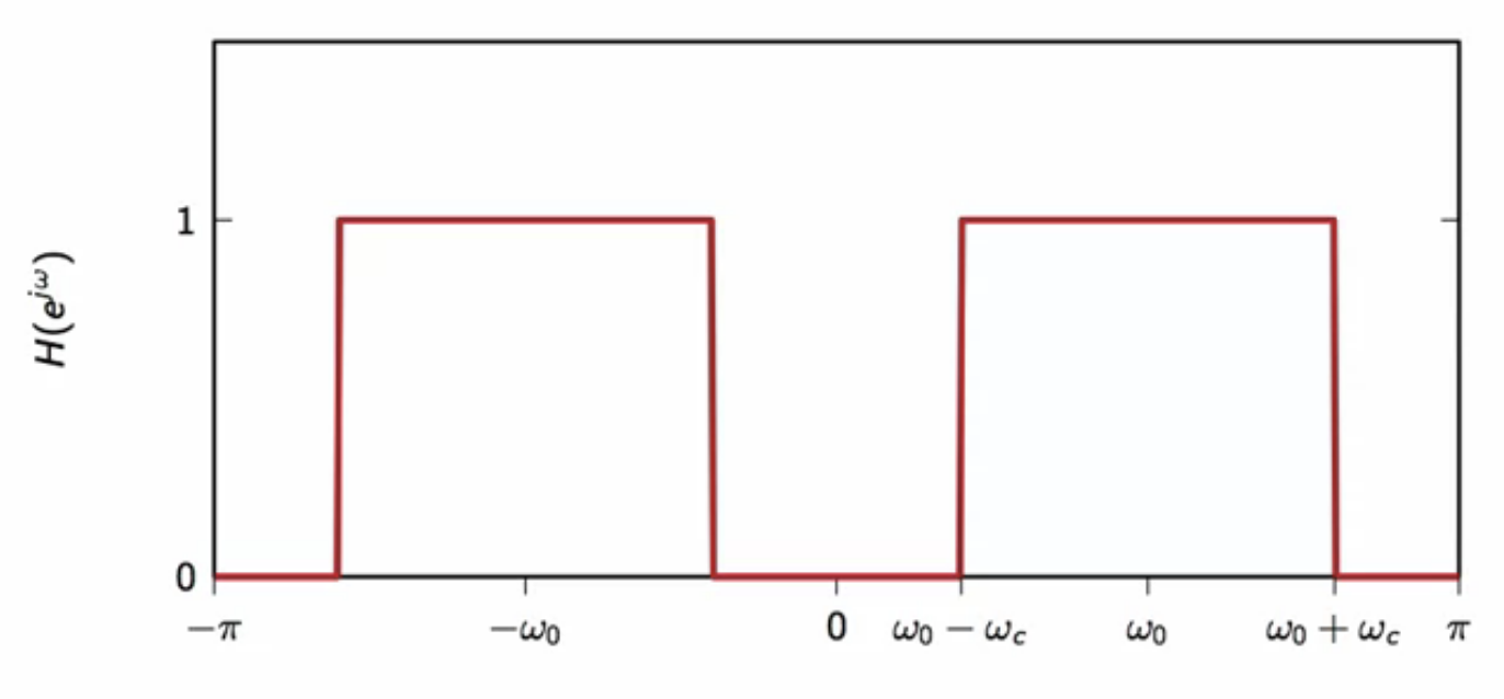
fig: ideal bandpass filter magnitude spectrum
- this is derived from the ideal lowpass filter by modulating them with a cosine wave
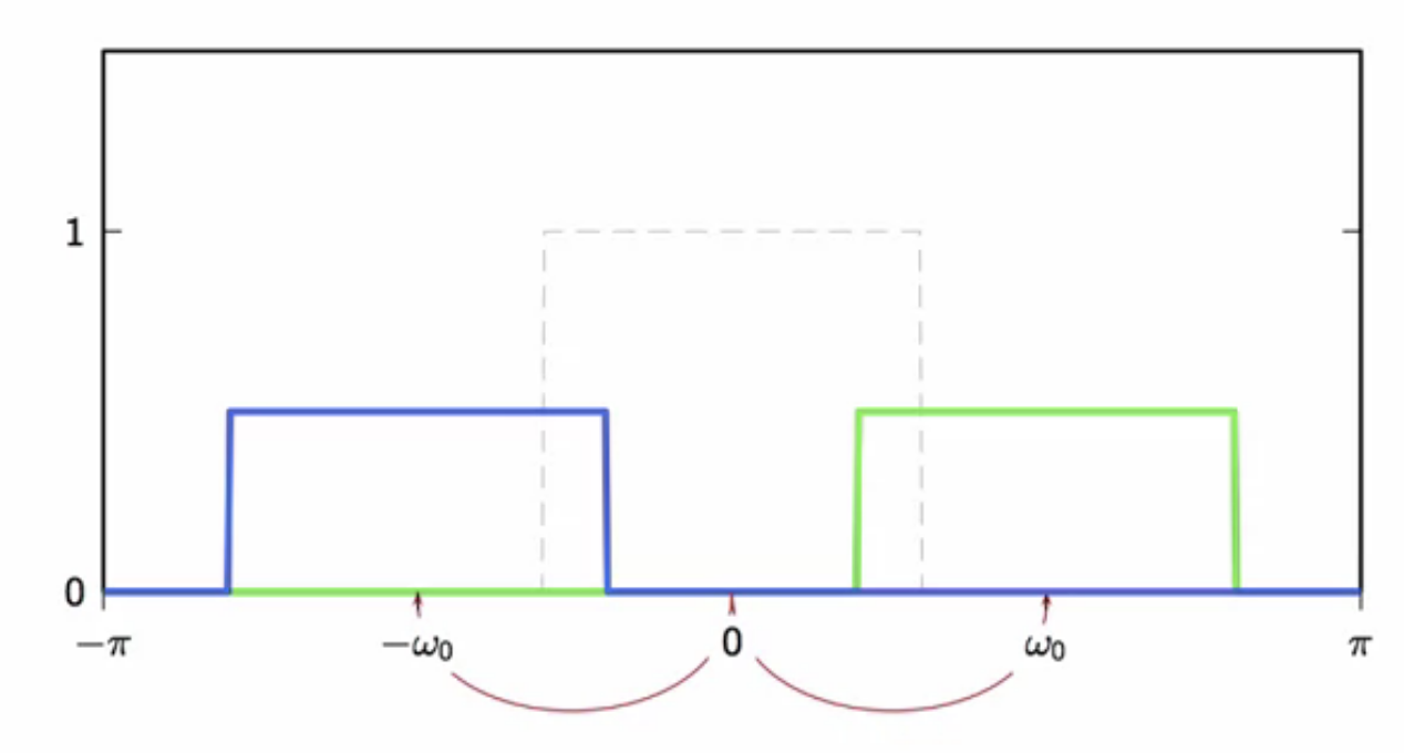
fig: ideal lowpass filter modulated with cosine wave to obtain ideal bandpass
formal ideal bandpass filter
demodulation - frequency domain
- time domain demodulation concepts
- apply sinusoidal modulation to
- demodulate by multiplication with carrier
- demodulated signal contains unwanted high frequency components
- these unwanted high frequency components are filtered out with a lowpass filter
filtering a demodulated signal
-
consider a signal in the frequency domain
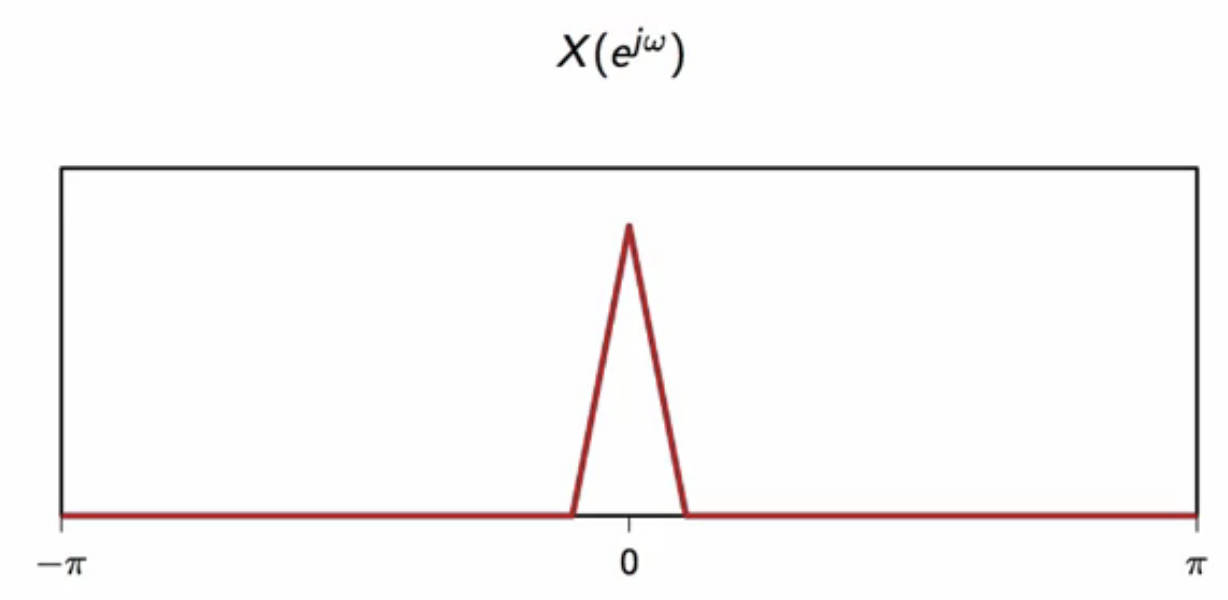
fig: signal in frequency domain
-
this is then modulated to get two half amplitudes at the modulation frequency
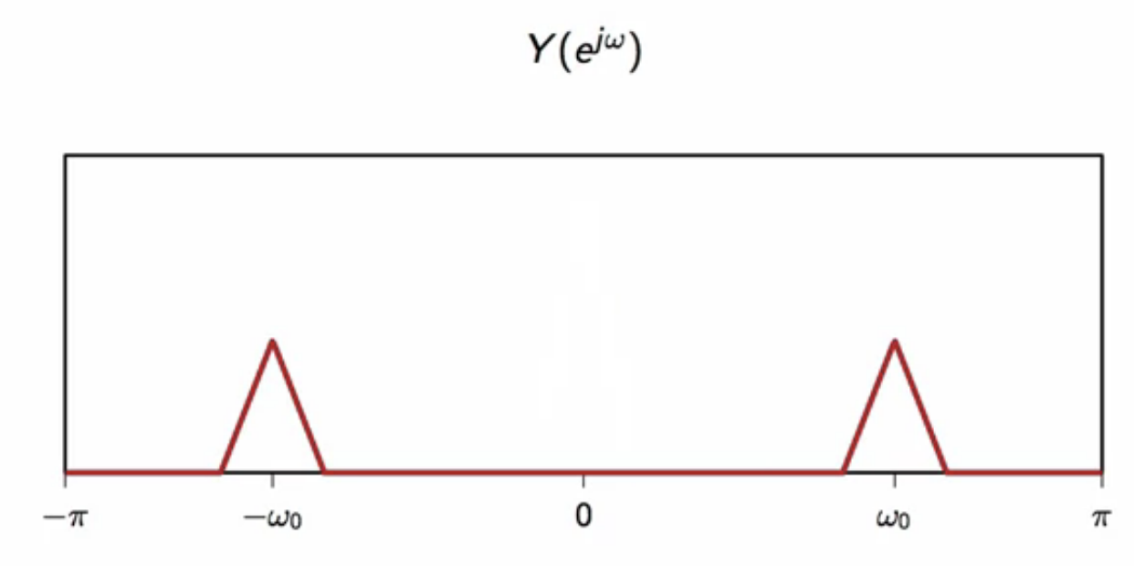
fig: modulate signal in frequency domain
-
this has a periodicity of in the frequency domain
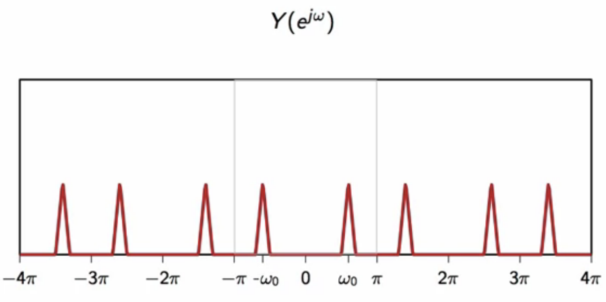
fig: extended bounds to reveal periodicity of modulated signal
-
this is then multiplied by to demodulate, which yields two components
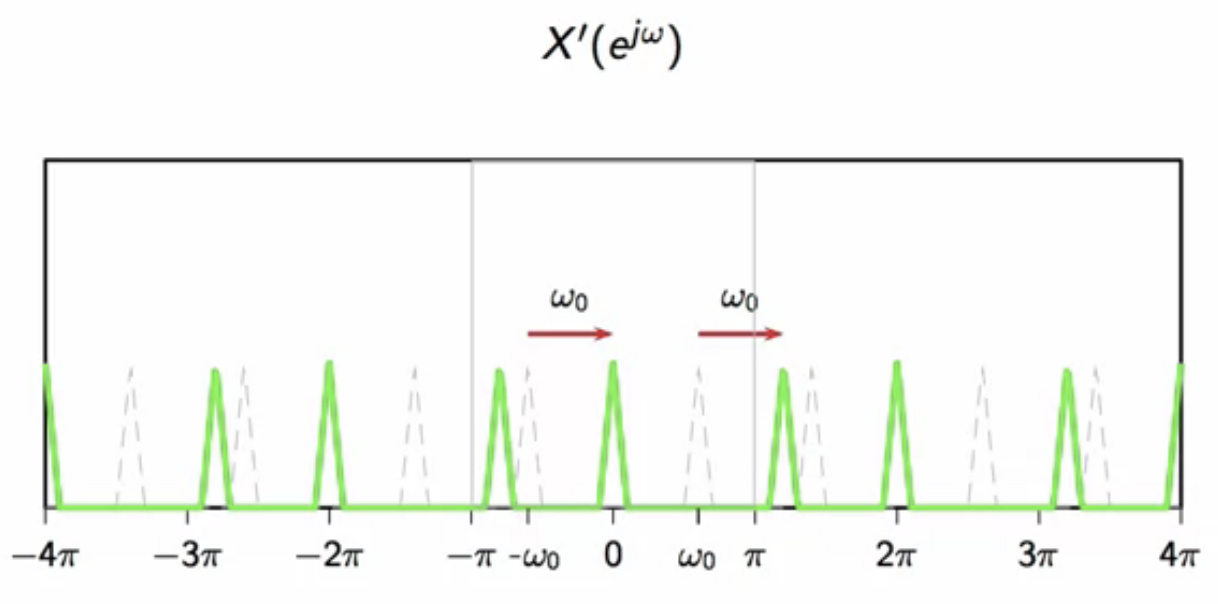
fig: one copy of the demodulated signal
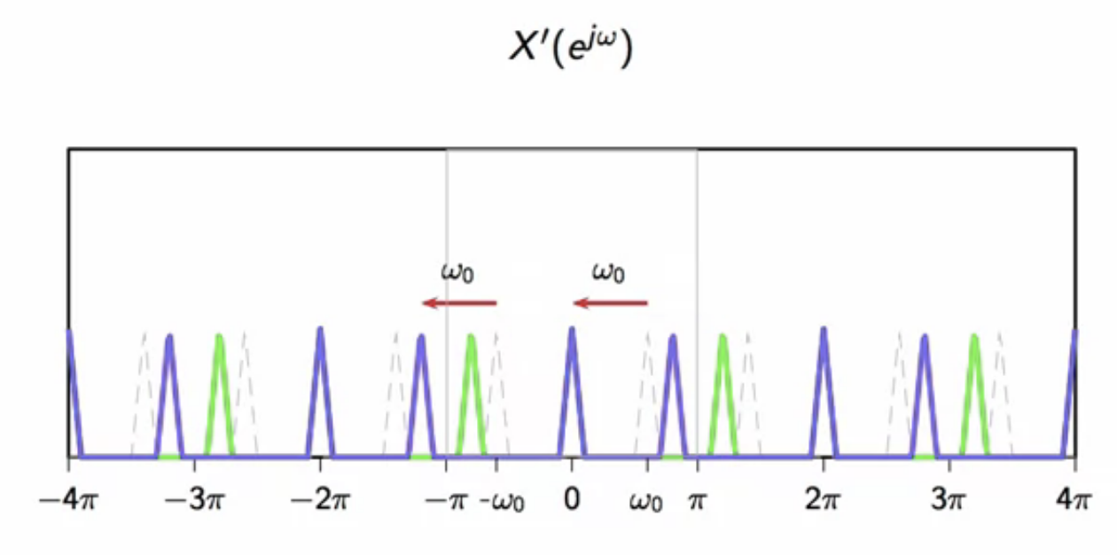
fig: second copy of the demodulated signal
-
to get the full demodulated signal, the two components are summed together to get
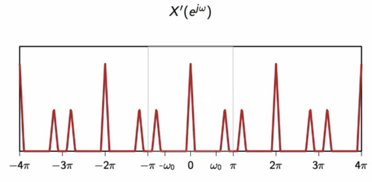
fig: sum of the components of the demodulated signal
-
examining a single period of this summation in
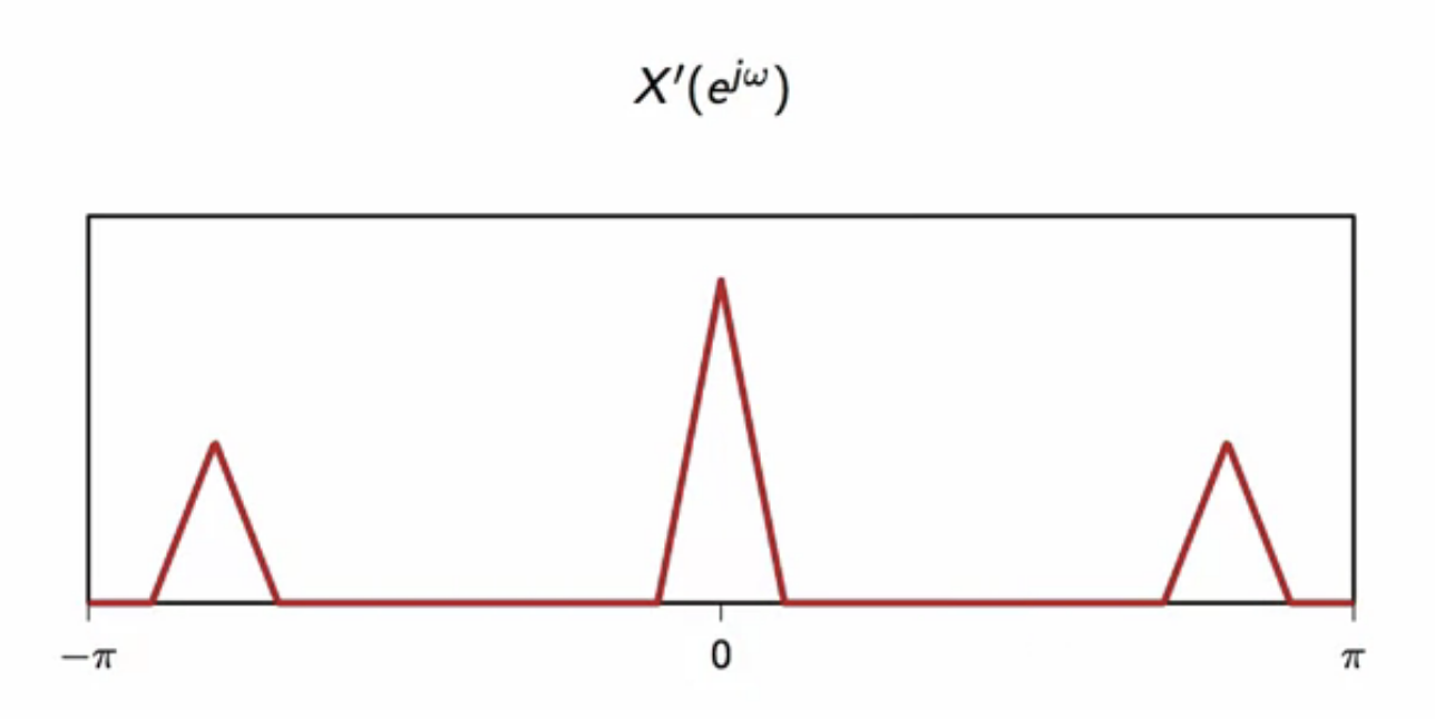
fig: single period (between ) of the summed signal
- here, spurious high frequency components near has to be filtered out
-
this is achieved using a lowpass filter
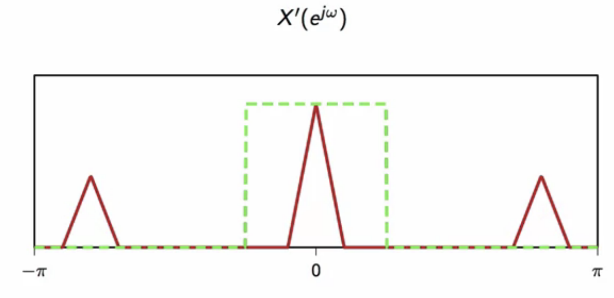
fig: low pass filter applied to demodulated signal
-
the original signal is obtained as the output of the filter
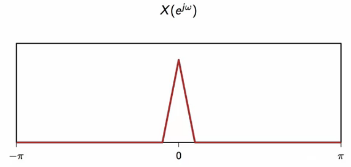
fig: original signal obtained from filtering demodulated signal