[DSP] W06 - Filter Design Approximations
contents
- ideal filters cannot be implemented in practice
- its impulse response is a two sided infinite support sequence
- strategies to approximate ideal filter behavior with practical structures are explored
imitation strategy
- replicate the structure of either the impulse response or the frequency response of ideal filters
- three fundamental methods to approximate ideal filters:
- impulse truncation
- the window method
- frequency sampling
- this strategy is rather limited
impulse truncation
- this is approximation by truncation of the impulse response of the impulse response
- procedure:
- pick (\omega_c)
- compute ideal impulse response (h[n] )
- truncate (h[n]) to a finite-support ( \hat{h}[n] )
- ( \tilde{h}[n] ) defines an FIR filter
- FIR approximation of length ((M = 2N + 1 ) \[ \hat{h}[n] = \Bigg { ]
pros
- MSE is minimized by symmetric impulse truncation filter around zero
- MSE computation between ideal and truncated filter
[ \begin{align}
MSE & = \frac{1}{2\pi} \int_{-\pi}^{\pi} \vert H(e^{j\omega}) - \hat{H}(e^{j\omega}) \vert^2 d\omega _
& = \vert\vert H(e^{j\omega}) - \hat{H}(e^{j\omega}) \vert\vert^2 _
_& = \vert\vert h[n] - \hat{h}[n] \vert\vert^2 _
_& = \sum{-\infty}^{\infty} \vert h[n] - \hat{h}[n] \vert^2 \end{align} ]
cons
- gibbs phenomenons occurs during approximation
- approximation always has some error to approximation near transition frequency
- the maximum error around the cutoff frequency is around 9% of the height of the jump
- regardless of (N)
- this is the gibbs error
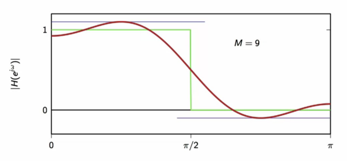
fig: ideal vs truncated - truncated (M=9)
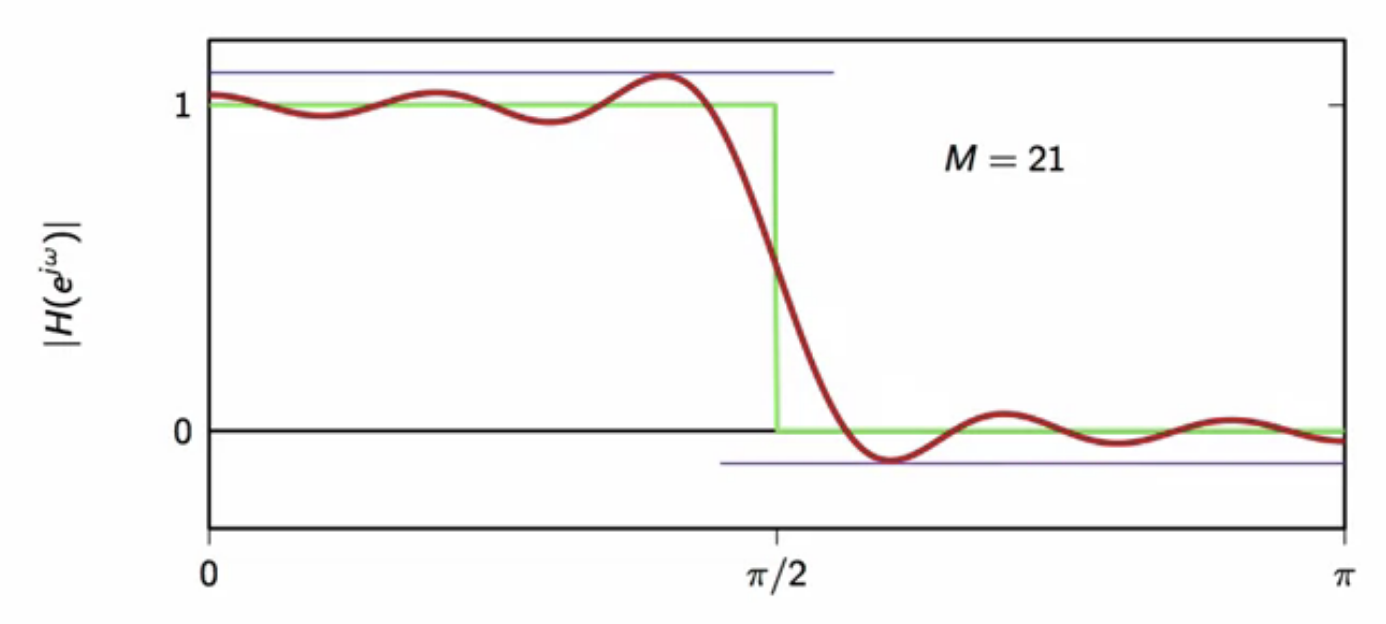
fig: ideal vs truncated - truncated (M=21)
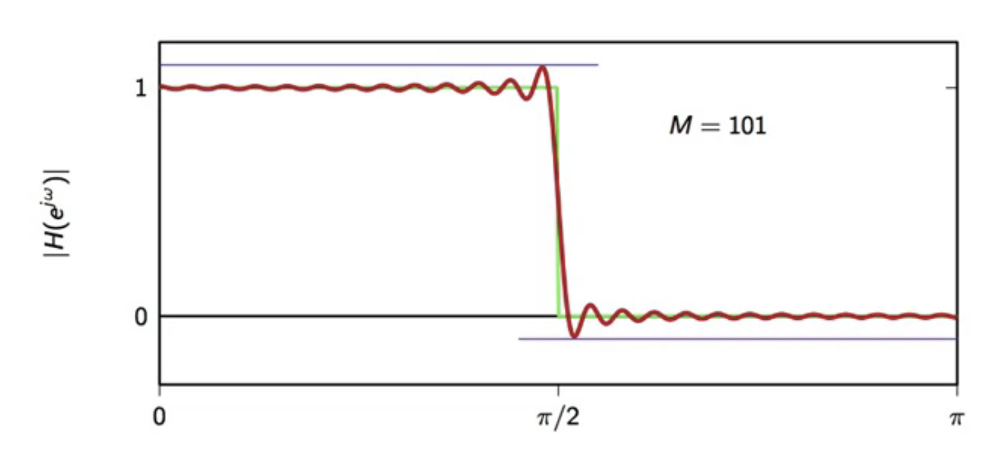
fig: ideal vs truncated - truncated (M=101)
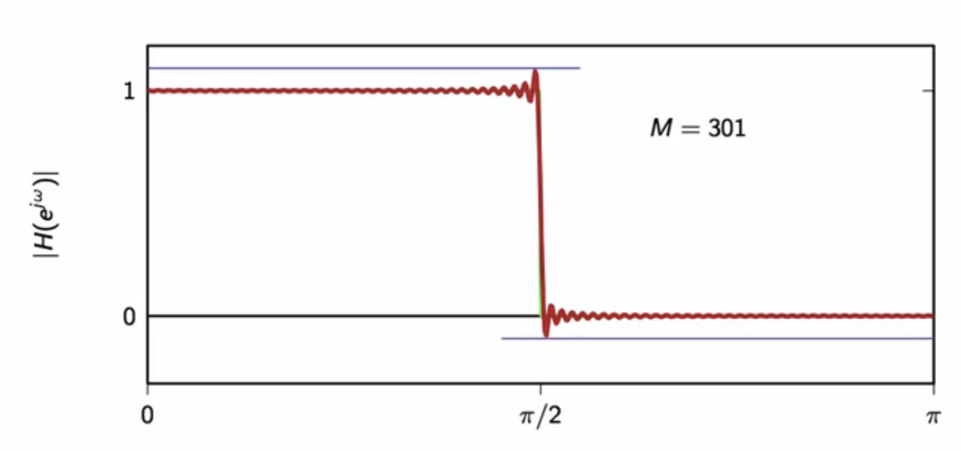
fig: ideal vs truncated - truncated (M=301)
- Gibbs phenomenon always occurs when a discontinuous function is approximated
modulation theorem
- convolution theorem states that the fourier transform of the convolution of two sequences is
- the product of the sequence fourier transforms in the frequency domain \[ DTFT { (x * y)[n] } = X(e^{j\omega})Y(e^{j\omega}) ]
- modulation theorem gives the result for the fourier transform of the product of two sequences
- says fourier transform of product of two sequences is the convolution of their fourier transforms in the frequency domain \[ DTFT { x[n]y[n] } = (X*Y)(e^{j\omega}) ]
convolution of DTFTs
- in the space of infinite support sequences ( \mathbb{C}^\infty )
- convolution is defined in terms of the inner product between sequences
- convolution between ( x ) and ( y ) is the inner product between
- ( x ) conjugated and
- ( y ) time reversed and delayed by ( n )
[ \begin{align}
(x y)[n] & = \langle x^ [k], y[n-k] \rangle
& = \sum_{n = -\infty}^{\infty} x[k]y[n-k] \
\end{align}
]
- similarly, in the space of DTFTs (L_2([-\pi,\pi]) ):
- the convolution of DTFTs is defined as
[ \begin{align}
(X Y)(e^{j\omega}) & = \langle X^ (e^{j\sigma}), Y^* (e^{j(\omega - \sigma)}) \rangle d\sigma
& = \frac{1}{2\pi} \int_{-\pi}^{\pi} X (e^{j\sigma})Y(e^{j(\omega - \sigma)}) d\sigma
\end{align} ]
- the convolution of DTFTs is defined as
[ \begin{align}
(X Y)(e^{j\omega}) & = \langle X^ (e^{j\sigma}), Y^* (e^{j(\omega - \sigma)}) \rangle d\sigma
- modulation theorem proof can be found in DSP textbooks and in the reference
\[ IDFT { (X * Y)(e^{j\omega}) } = x[n]y[n] ]
window function
- window function method is a generalization of the impulse truncation method where a different window shape may be used
- truncation can be expressed as follows
\[ \hat{h}[n] = h[n]w[n]
\text{where } w[n] \text{ is the truncation (window) function}
w[n] = \Bigg { ]
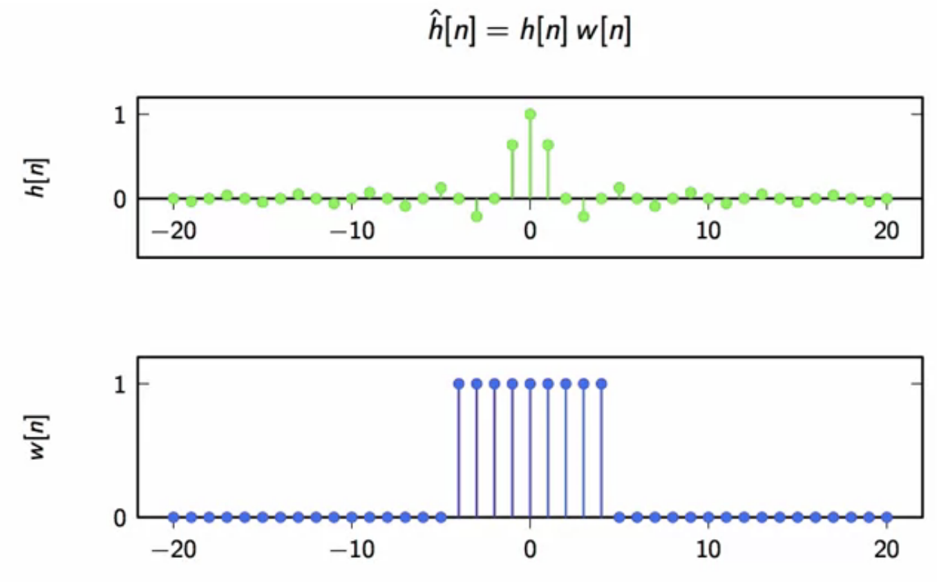
fig: the ideal filter impulse response (top) and the truncation multiplier signal (bottom)
- given this, the goal is to find the fourier transform of the truncated filter \[ \hat{H}(e^{j \omega}) = ? ]
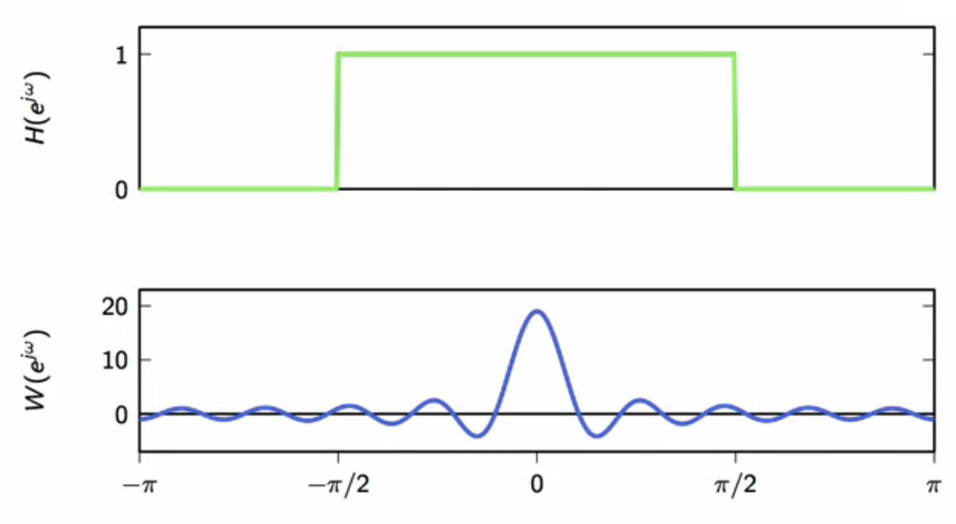
fig: fourier transforms of the ideal filter impulse response (top) and the truncation multiplier signal (bottom)
[ ]
frequency domain
- graphically, the progression of the convolution of the implicit frequency domain convolution of
- ideal filter impulse response (top)
- truncation multiplier signal (bottom)
fig: low (\omega)
fig: (\omega) at transition
fig: (\omega) in ideal lowpass filter passband
fig: (\omega) deeper in ideal lowpass filter passband
fig: (\omega) at center of ideal lowpass filter passband
fig: (\omega) moving away from center of ideal lowpass filter passband
fig: (\omega) reaching exit of ideal lowpass filter passband
fig: (\omega) at other transition
fig: (\omega) in ideal lowpass filter stopband
- as observed above, the shape of the fourier transform of the approximate filter depends on the fourier transform of the truncation multiplier function ( w[n] )
- the mainlobe is the red lobe in the below fig
- the width of this mainlobe determines how quickly the approximated filter will transform from stopband to passband
- the area in red in below fig are the sidelobes
- the amplitude of the sidelobes determines the amount of error on either sides of the passband at the transition
- i.e. the gibbs error fig: fourier transform of the truncation multiplier function ( w[n] )
- the amplitude of the sidelobes determines the amount of error on either sides of the passband at the transition
- desired qualities in the fourier transform of the truncation multiplier function ( w[n] ):
- narrow mainlobe so transition is quick
- small sidelobes for minimal gibbs error
- short window so FIR is efficient
- these requirements are conflicting
- triangular window is an alternative to the rectangular window
- this reduces the gibbs error
- tradeoff is a wider main lobe
- so slow transformation between passband and stopband
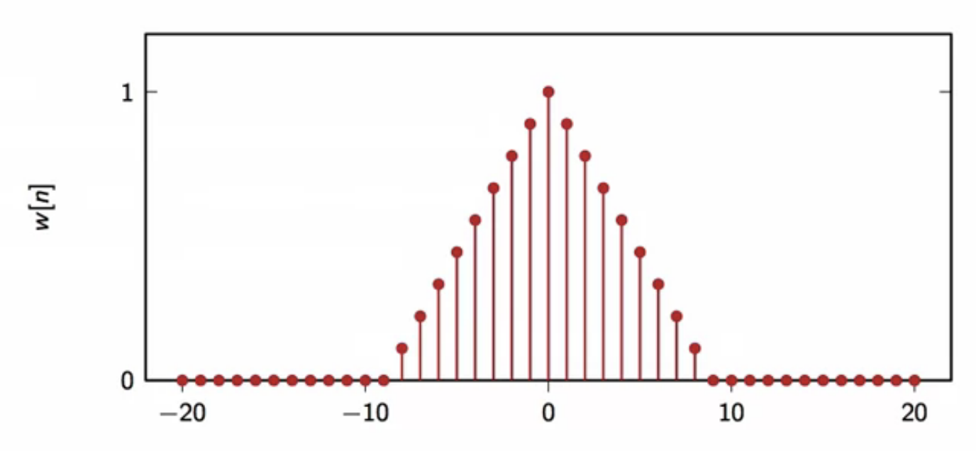
fig: triangular window
frequency sampling
- a different method of approximating an ideal filter
- procedure
- draw desired frequency response ( H(e^{j\omega}) ) in frequency domain
- sample (M) values @ regular intervals of ( \omega_k = \Big( \frac{2\pi}{M}k \Big) ) between ([-\pi,\pi])
- compute IDFT of samples values
- use result as an (M)-tap impulse response ( \hat{h}[n] )
- this impulse response is the approximated filter characteristic
- example:
fig: desired response expressed (drawn) in frequency domain
fig: 11 samples taken from desired response
fig: rearrange sampled values according to DFT notation
fig: compute IDFT - impulse response of approximated filter
pros
- quick and dirty method to get an approximated filter
cons
- not optimal
- DFT of the obtained finite-support filter has to converted to the DTFT representation
- DTFT is optimal only for infinite-length signals
- DFT is optimal for finite-support signals
- in the process of converting DFT to DTFT, there is interpolation of multiple signals involved
- frequency response is the interpolation of frequency samples
- interpolator is transform of N-tap rectangular window (again)
- so no control over mainlobe and sidelobes
- gibbs error reigns supreme
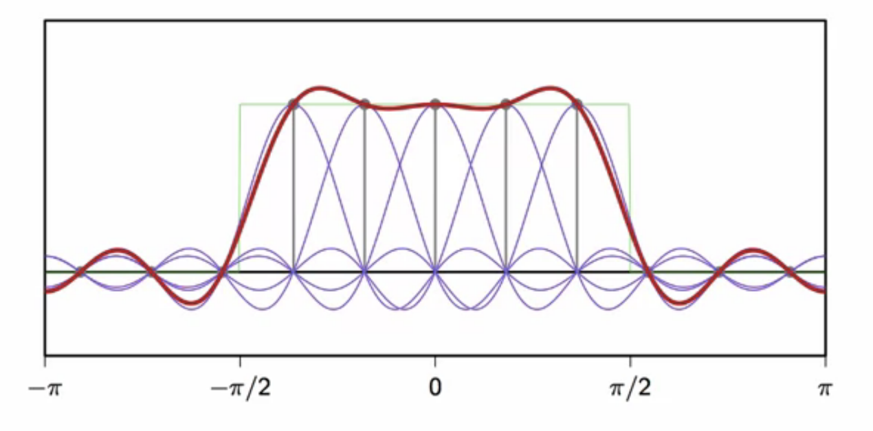
fig: green - desired frequency response; blue - frequency sample interpolation; red - DTFT of obtained filter