[DSP] W06 - Zero-Pole Plot for Filter Design
contents
simple filters
- simple filters solve a lot of dsp problems
- mastering simple filters is important
- low order transfer functions can be easily understand just by looking at their zero-pole plot
- their design and tuning is intuitive
- simple filters can be derived from ideal filters by tuning the zero-pole plot
- complex poles and zeros in complex conjugate pairs are added to the zero-pole plot to obtain real filters
- zero and poles position is set as required to enable desired filter function
- simple filter examples
- moving average
- leaky integrator
leaky-integrator
- let only low frequencies pass
- finds application in
- removing high frequency components, which usually is noise
- useful in audio, communication and control systems
filter structure
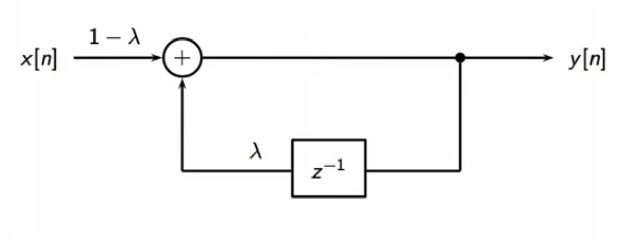
fig: leaky-integrator filter structure block diagram
filter equations
\[ \text{leaky-integrator transfer function} \
\begin{align}
H(z) & = \frac{(1-\lambda)}{1-\lambda z ^{-1}} \
\
\end{align}
\]
\[ \text{leaky-integrator CCDE} \
\begin{align}
y[n] & = (1 - \lambda)x[n] + \lambda y[n-1] \
\end{align}
\]
zero-pole plot
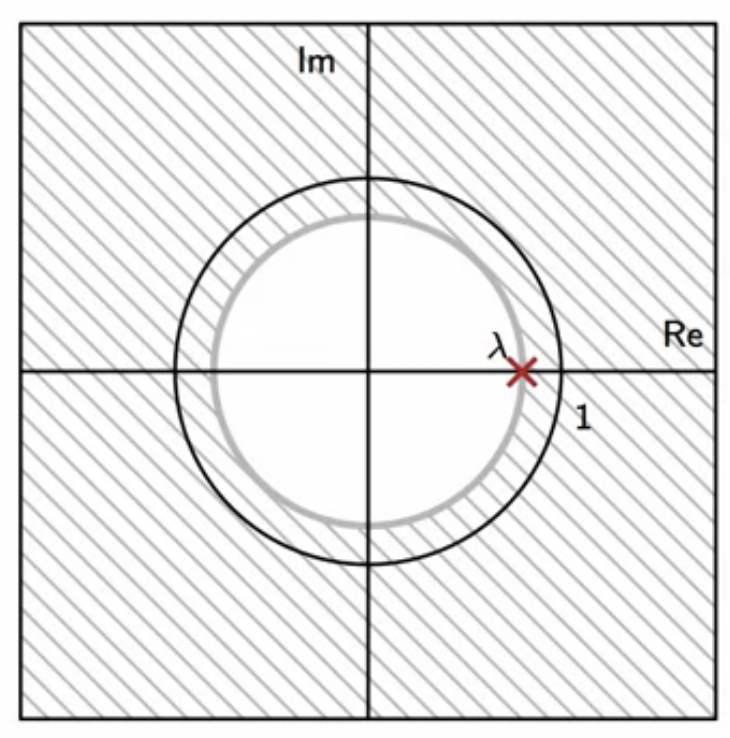
fig: leaky-integrator zero-pole plot
- \(\lambda \) is the only pole in the leaky-integrator zero-pole plot
- it is a real pole
- no complex conjugates
frequency domain
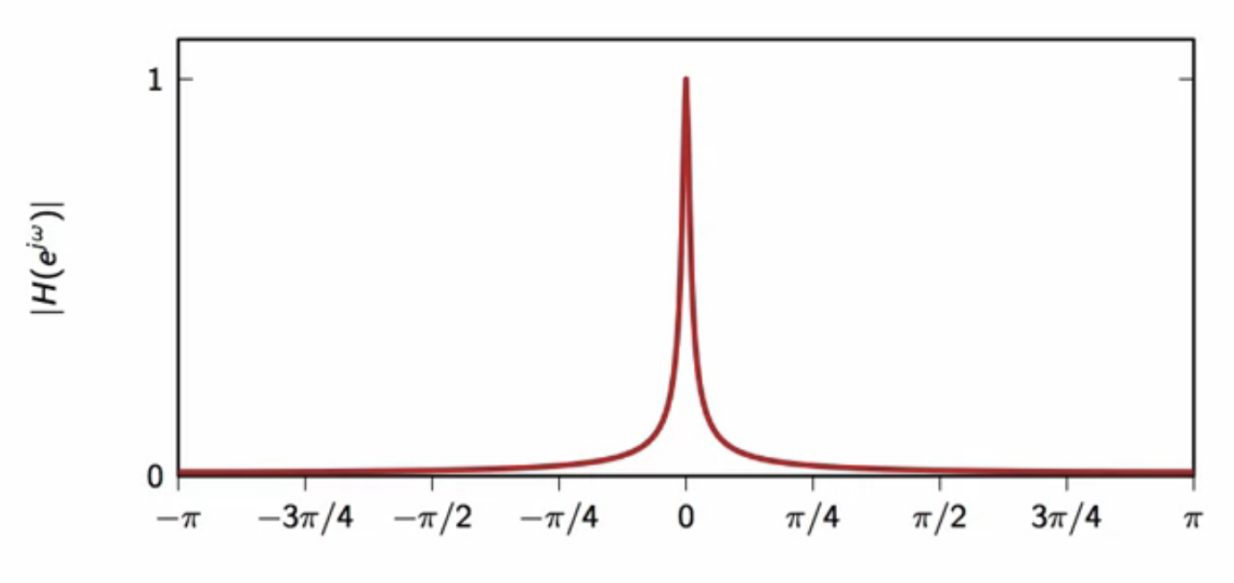
fig: leaky-integrator frequency response \(\lambda = 0.98\)
- gets more concentrated at \(0\) as \(\lambda \) get closer to \(1\)
resonator
- a resonator is a narrow bandpass filter
- maybe derived from a leaky integrator
- filter mechanism is to shift the passband of the leaky-integrator
- used to detect the presence of a sinusoid at a given frequency
- useful in communication systems and DTMF (dual-tone-multi-frequency) signals
- DTMF (dual-tone-multi-frequency) signals
- used to identify which key has been pressed
- at the central telephone exchange
zero-pole plot
- the pole at \(\lambda \) of the leaky integrator
- generate a complex conjugate pole to make the filter realizable
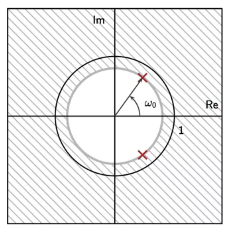
fig: resonator zero-pole plot (shifted leaky-integrator pole)
- this shifts the passband
- may be tuned to the desired frequency \(\omega_0\)
filter block
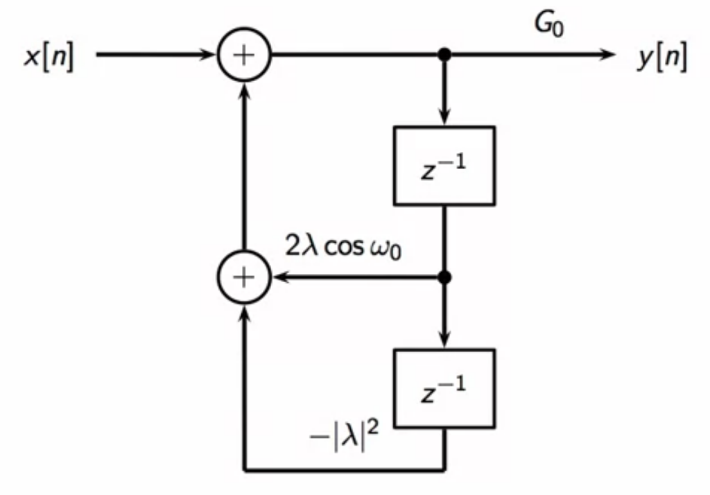
fig: resonator filter structure block diagram
- simple second order feedback loop
- with two delays
- first delay scaled by one constant
- first delay scaled by a different constant
filter equations
\[ \text{resonator transfer function} \
\
\begin{align}
H(z) & = \frac{G_0}{(1-p z^{-1})(1-p^* z^{-1})} \
\
p & = \lambda e^{j \omega}
\
\end{align}
\]
\[ \text{resonator CCDE} \
\
\begin{align}
y[n] & = G_0 x[n] - a_1 y[n-1] - a_2 y[n-2] \
\
a_1 & = 2 \lambda \cos \omega_0 \
a_2 & = - \vert \lambda \vert ^ 2\
\end{align}
\]
frequency response
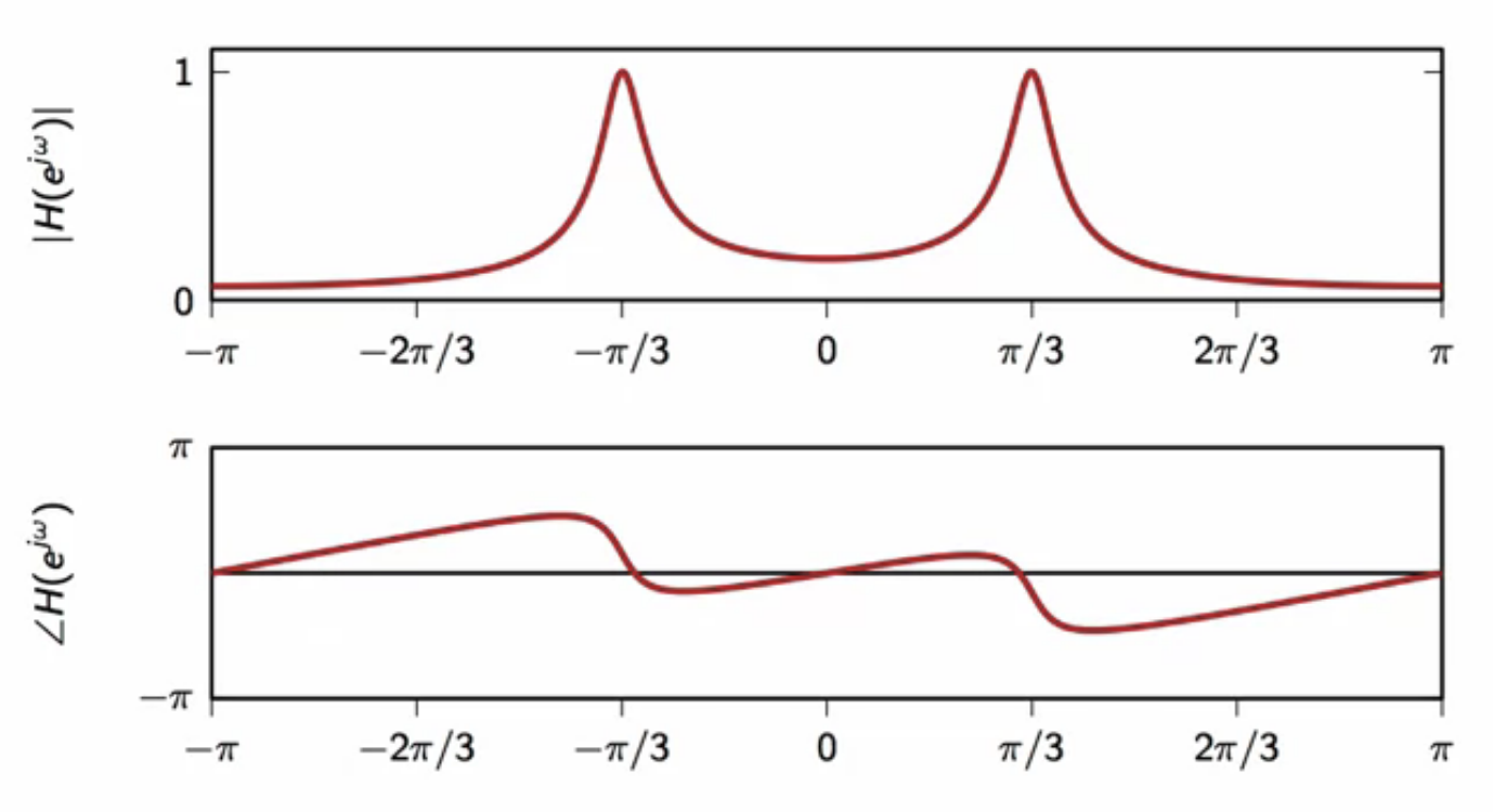
fig: resonator frequency response (\(\omega_0 = \frac{\pi}{3}; \lambda = 0.9\))
- two peaks centered around \(\omega_0\)
- here \(\omega_0 = \frac{\pi}{3} \)
- phase is non-zero
- not very selective as passband is spread out
- choose \( \lambda \) closer to \(1\) for more selectivity
DC removal filter
-
DC: direct current
- a DC balanced signal has zero-mean
\[ \lim_{N \rightarrow \infty} \sum_{n = -N}^{N} x[n] = 0
\]
- no direct current component, i.e. no offset from center
- its DTFT at zero is zero
- signals are DC balanced because
- DC offset doesn’t carry any information
- but wastes current in circuits
- a DC removal filter makes a signal DC balanced
- removes DC bias from a non zero-centered signal
- by removing frequency component at \(\omega = 0 \)
zero-pole plot
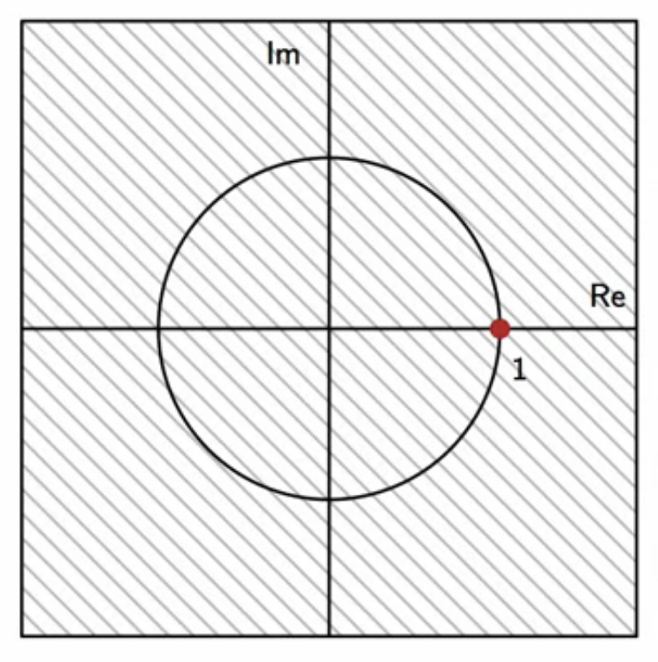
fig: DC removal filter zero-pole plot
- place zero at \(z = 1\)
- point on complex plane where \(\omega = 0\)
filter equations
\[ \text{DC removal filter transfer function} \
\
\begin{align}
H(z) & = 1 - z^{-1} \
\
\end{align}
\]
\[ \text{DC removal filter CCDE} \
\
\begin{align}
y[n] & = x[n] - x[n-1] \
\
\end{align}
\]
frequency response
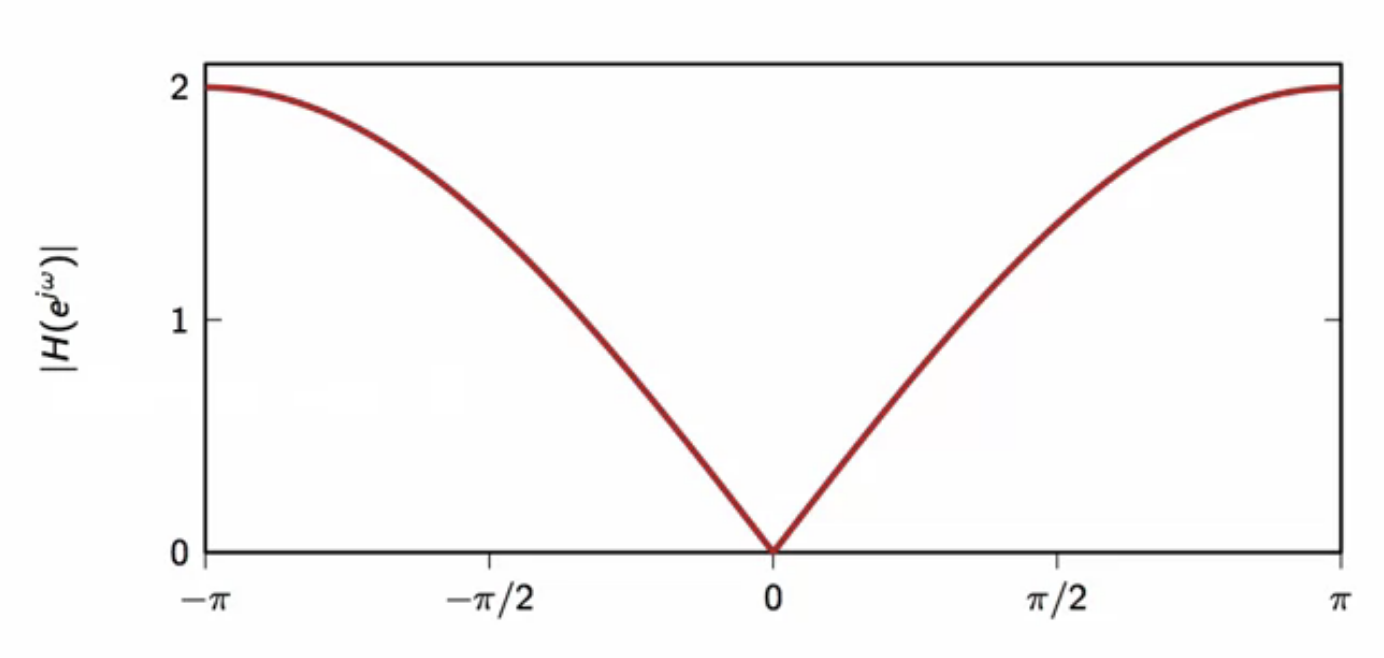
fig: DC removal filter frequency response
- frequency component at \( \omega = 0 \) is \(0 \)
- but the response introduces an attenuation in surrounding frequencies
- in almost the entire response in \([-\pi,\pi] \)
- which is not acceptable
- a notch behavior design is needed to avoid this
- DC notch filter is explored
DC Notch
- to avoid undesired attenuation in frequencies
- surrounding \( \omega = 0 \)
- in almost the entire response in \([-\pi,\pi] \)
- DC removal filter design needs ot be improved
- going back to the circus-tent method, the zero-pole plot of the DC removal filter is modified
zero-pole plot
- in the DC removal filter zero-pole plot
- a pole pushes up the frequency response magnitude, while a zero pushes it down
- so a pole is added close to the center, inside the unit circle
- the location of the pole is given by \(\lambda \)
- like the pole of the leaky-integrator zero-pole plot
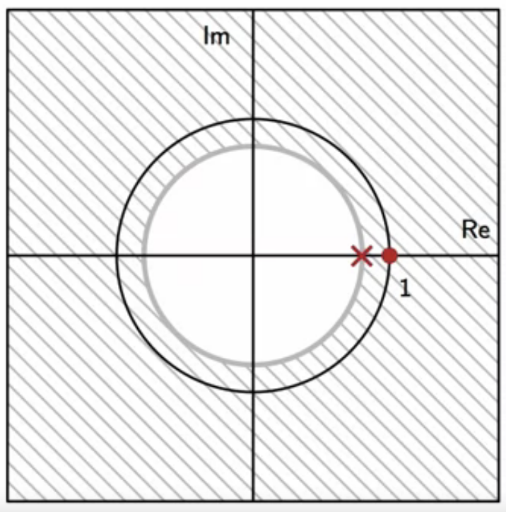
fig: DC notch zero-pole plot
- this is a combination of a DC removal zero at \( 1 \) and
- a leaky-integrator pole
filter equations
\[ \text{DC notch transfer function} \
\
\begin{align}
H(z) & = \frac{1-z^{-1}}{1 - \lambda z^{-1}} \
\
\end{align}
\]
\[ \text{DC notch filter CCDE} \
\
\begin{align}
y[n] & = \lambda y[n-1] + x[n] - x[n-1] \
\
\end{align}
\]
frequency response
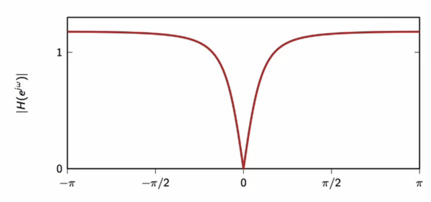
fig: DC notch frequency response \( \lambda = 0.7 \)
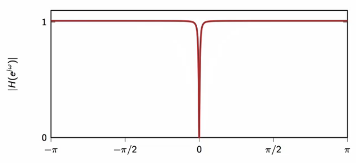
fig: DC notch frequency response \( \lambda = 0.98 \)
- as \( \lambda \) gets closer to \(1\)
- filter notch gets very narrow
- width of frequency attenuation may be tuned with \(\lambda \)
filter block

fig: resonator filter structure block diagram
- delay is shared between feedforward and the feedback loop
hum removal
- a filter derived from DC notch
- a DC notch removed frequencies only at \(\omega = 0\)
- hum removal shifts the notch to remove a non-zero frequency
- useful in the music studio
- amplifiers pick up the hum from the electric mains
- 50Hz - europe
- 60HZ - north america
- this may be removed with a hum removal filter
zero-pole plot
- the hum removal strategy is similar to deriving a resonator from a leaky-integrator
- the real pole of the leaky is moved to complex conjugate ones
- this shifts the passband central frequency
- resulting in a resonator
- similarly, the real pole of the DC notch is moved to complex complex ones
- the notch central frequency moves to a non-zero with this act
- the resulting filter is called a hum remover
- as its popular application is removing hum from electrical instruments
- the real zero of the DC notch is moved to complex conjugate ones
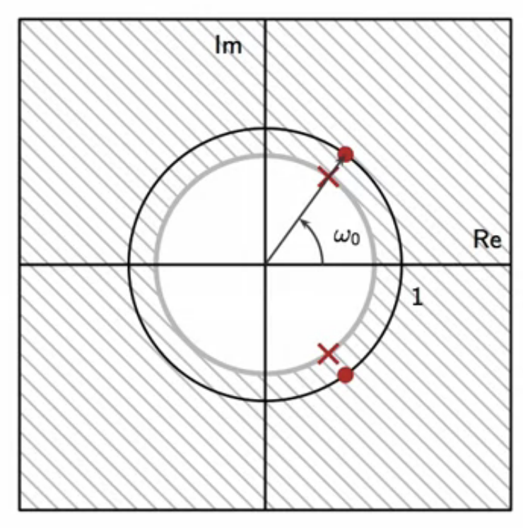
fig: hum removal zero-pole plot
filter equations
\[ \text{hum removal transfer function} \
\
\begin{align}
H(z) & = \frac{ ( 1 - e^{j \omega_0} z^{-1} ) (1 - e^{-j \omega_0} z^{-1} ) }{ (1 - \lambda e^{j \omega_0} z^{-1}) (1 - \lambda e^{-j \omega_0} z^{-1}) } \
\
\end{align}
\]
frequency response
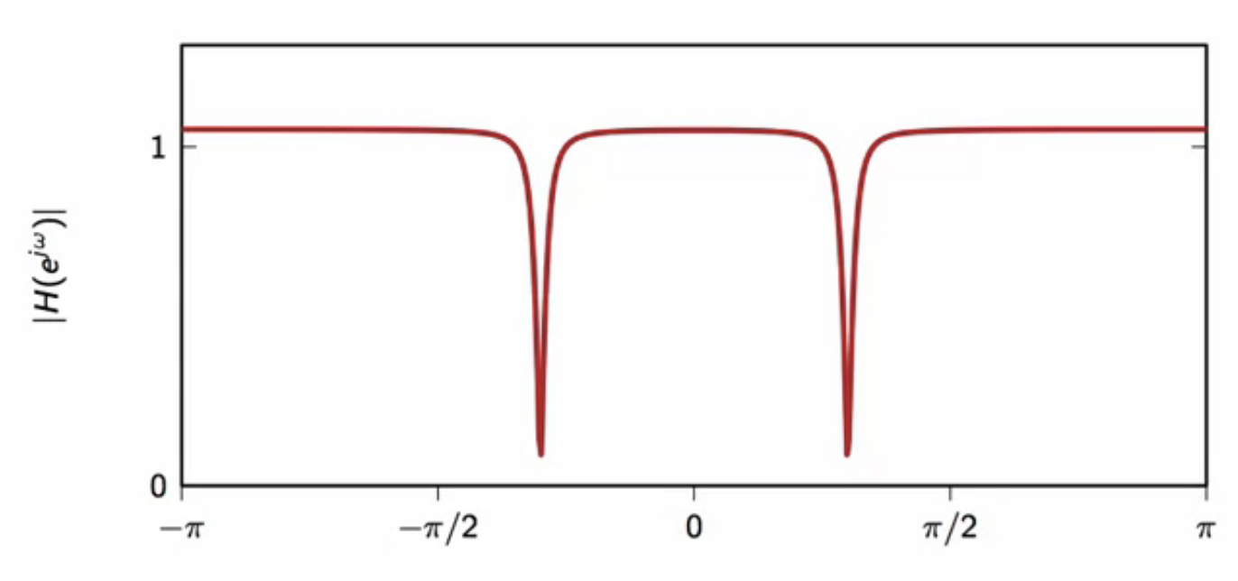
fig: hum removal frequency response \( \lambda = 0.95 \)
- notches at \(\omega_0 \leq = 0\)
- removes frequency component at \( \omega_0 \)
filter block
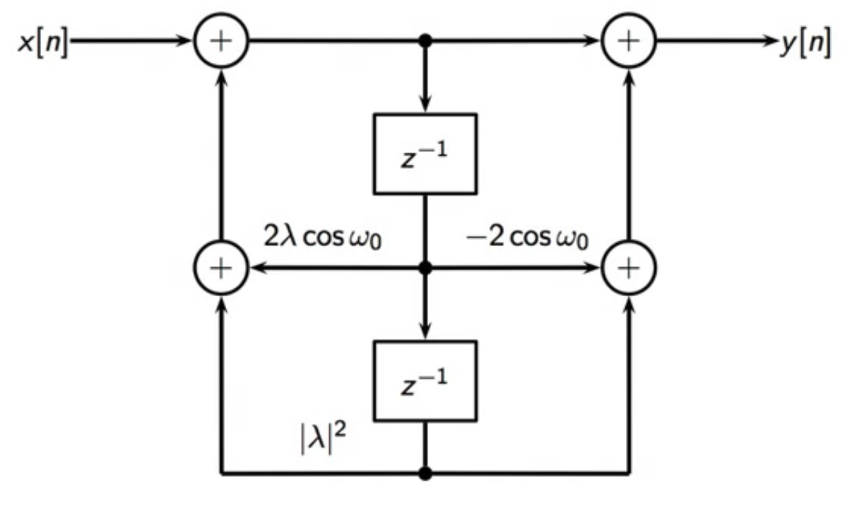
fig: hum removal filter structure block diagram
- two delay stages
- each scaled differently
- delay is shared between feedforward and the feedback loop