[DSP] W08 - Modulation and Demodulation
contents
- the signal is prepared for transmission through the channel constraints
- this includes modulating the signal
- on the receiver end, the signal is demodulated
- then is decoded to estimate the encoded information
- estimate because there is error in
- the encoding
- the decoding
- also noise is added in the channel during propagation
signal preparation
- the signal flows through the following
- signal in bitstream
- scrambler makes it random and white
- power spectral density is constant across full specrtrum
- QAM mapper encodes bitstream to a complex valued symbol
- resulting in \( a[n] \)
- upsampler fits encoded signal to channel bandwidth
- K times more samples
- lowpass raised cosine remove the copies obtained after digital upsampling
- cutoff frequency \( \frac{\pi}{K} \)
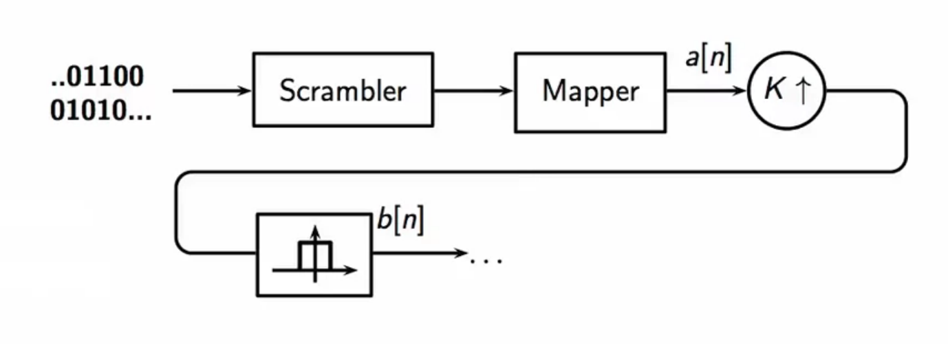
fig: QAM transmitter schematic
- the signal thus obtained with a QAM decoder is \(b[n]\) \[ b[n] = b_r[n] + jb_i[n] \]
- \(b[n]\) is a complex-valued baseband signal
- having been subjected upsampling, its bandwidth is meets the carrier constraint
- but does not sit in the bounds of the carrier’s bandwidth
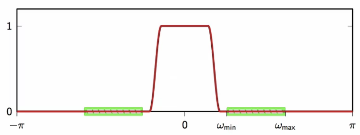
fig: carrier bandwidth availability (green) and \(b[n]\) baseband (red)
modulation
- modulation is the process of modifying the complex baseband that has the same size of the carrier bandwidth to sit exactly in the specified bandwidth
- a complex baseband cannot be transmitted over a real physical channel
- to fully reconstruct the information at the other end
- so the complex baseband has to be made real before transmission
discrete-time domain
- let \( \omega_c \) be the center frequency of the channel bandwidth
- then, the modulated, real baseband is obtained as follows
\[ \begin{align}
s[n] & = Re\{ b[n] e^{j\omega n} \} \
& = Re \{ (b_r[n] + jb_i[n])( \cos \omega_c n + j \sin \omega_c n ) \} \
& = b_r[n] \cos \omega_c n - b_i [n] \sin \omega_c n \
\end{align} \] - here,
- the real part of the complex baseband is modulated with a cosine and
- in-phase component
- the imaginary part is modulated with a sine
- quadrature component
- both are at the carrier bandwidth central frequency
- also, they are orthogonal to each other i.e. in quadrature
- this is the source of the name QAM used to encode with the complex number symbols
- the real part of the complex baseband is modulated with a cosine and
- \( s[n] \in \mathbb{N} \)
- is used at the receiver end to recover the complex baseband signal
complex discrete-frequency domain
- before modulation
- real and imaginary component spectrums separated
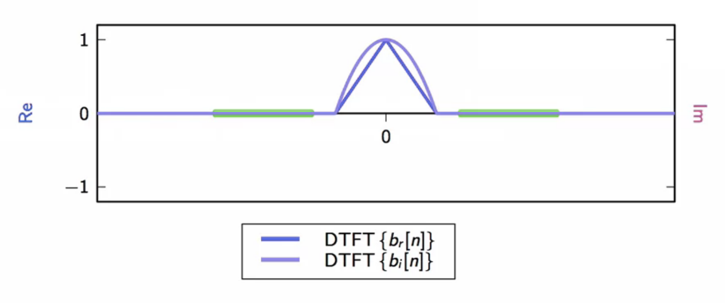
fig: carrier bandwidth availability (green); \(b[n]\) baseband real part (blue); \(b[n]\) baseband imaginary part (pink)
- after modulation
- real and imaginary modulated component spectrums separated
- the real part is symmetric
- the imaginary part is anti-symmetric
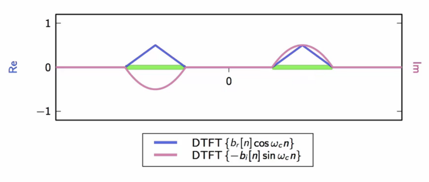
fig: carrier bandwidth availability (green); \(b[n]\) baseband modulated real part (blue); \(b[n]\) baseband modulated imaginary part (pink)
demodulation
- demodulation is achieved by multiplying received signal by the carrier signal
- in the QAM scenario, there are two carriers in the received signal
- one sine and one cosine
in-phase part extraction
- begin with multiplying by cosine to extract the real part of the received baseband
\[ \begin{align}
s[n] \cos \omega_c n & = b_n[n] \cos^2 \omega_c n - b_i[n] \sin \omega_c n \cos \omega_c n \
& = b_r[n] \frac{1 + \cos 2 \omega_c n}{2} - b_i[n] \frac{2 \sin 2 \omega_c n}{2} \
& = \frac{1}{2} b_r[n] + \frac{1}{2} ( b_r[n] \cos 2 \omega_c n - b_i[n] \sin 2 \omega_c n ) \
\end{align}
\]
- the frequency component reveals one half of the real part of the transmitted and received signal
- matched filter configuration: same raised cosine used at the transmitter is used at the receiver
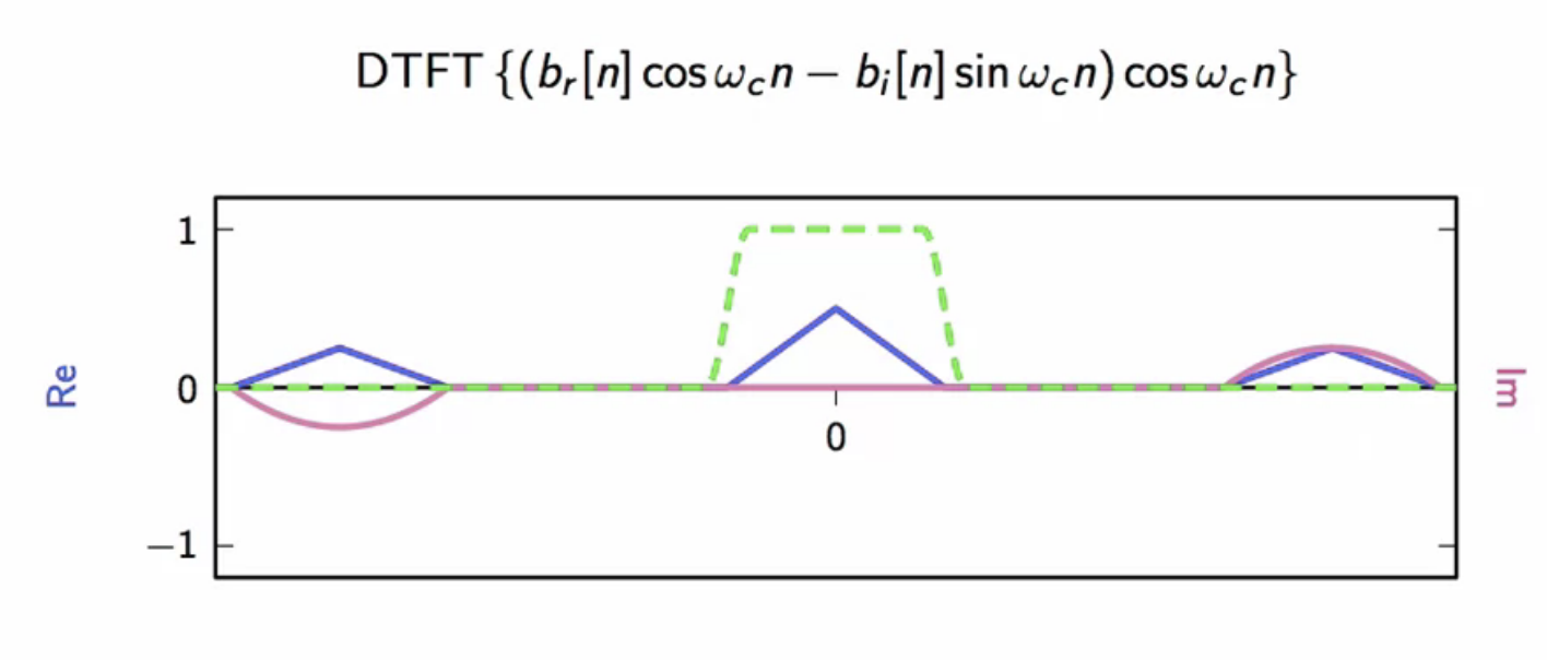
fig: frequency domain of signal after multiplying with cosine wave (blue); raised cosine lowpass applied (green)
- the raised cosine will eliminate everything but the real part of the transmitted baseband
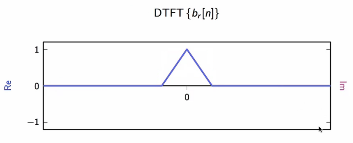
fig: recovered real part of transmitted baseband
quadrature part extraction
- multiply by sine to extract the imaginary part of the transmitted baseband
\[ \begin{align}
s[n] \sin \omega_c n & = b_r[n] \cos \omega_c n - b_i[n] \sin^2 \omega_c n \
& = - \frac{1}{2} b_i[n] + \frac{1}{2} ( b_r[n] \sin 2 \omega_c n - b_i[n] \cos 2 \omega_c n ) \
\end{align}
\]
- the frequency band looks similar to the demodulation of the in-phase part
- the core signal is extracted with a raised cosine lowpass
design example
- to be explored is a system that enables encoding and transmission of complex-valued sequence over a real-valued channel
QAM transmitter
- the signal in a QAM transmitter is processed as follows:
- signal in bitstream
- scrambler makes it random and white
- power spectral density is constant across full specrtrum
- QAM mapper encodes bitstream to a complex valued symbol
- resulting in \( a[n] \)
- upsampler fits encoded signal to channel bandwidth
- K times more samples
- lowpass raised cosine remove the copies obtained after digital upsampling
- cutoff frequency \( \frac{\pi}{K} \)
- the filtered signal is multiplied with complex exponential whose frequency is the central frequency of carrier bandwidth
- this results in a complex passband signal
- the real part of the complex baseband is extracted along with modulation
- this is sent to the DAC which propagates it into the channel
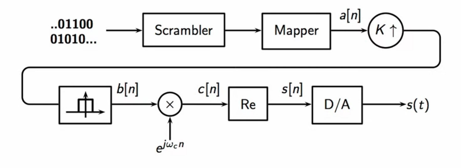
fig: QAM transmitter signal flow schematic
QAM receiver
- goal of the receiver to obtain the original bitstream which is the core information that was transmitted
- an ideal QAM receiver processes the received signal to retrieve that as follows:
- analog signal is received from the channel
- this analog signal is sampled with appropriate sampling rate
- signal is split into two parts to modulate with cosine and sine separately
- cosine demod results in the real part
- sine demod results in the imaginary part
- both demodulated signals go through their own lowpass filter
- matched filter configuration: same lowpass used at the transmitter
- the imaginary component is multiplied with complex root to and summed with the real part to construct an estimate of the transmitted baseband
- this is then subjected to downsampling
- thus obtained complex symbol sequence is passed through a slicer
- the bit chuck associated with the symbol is obtain so
- these chunks are assembled into a sequence and passed into a descrambler
- this recovers the original bitstream
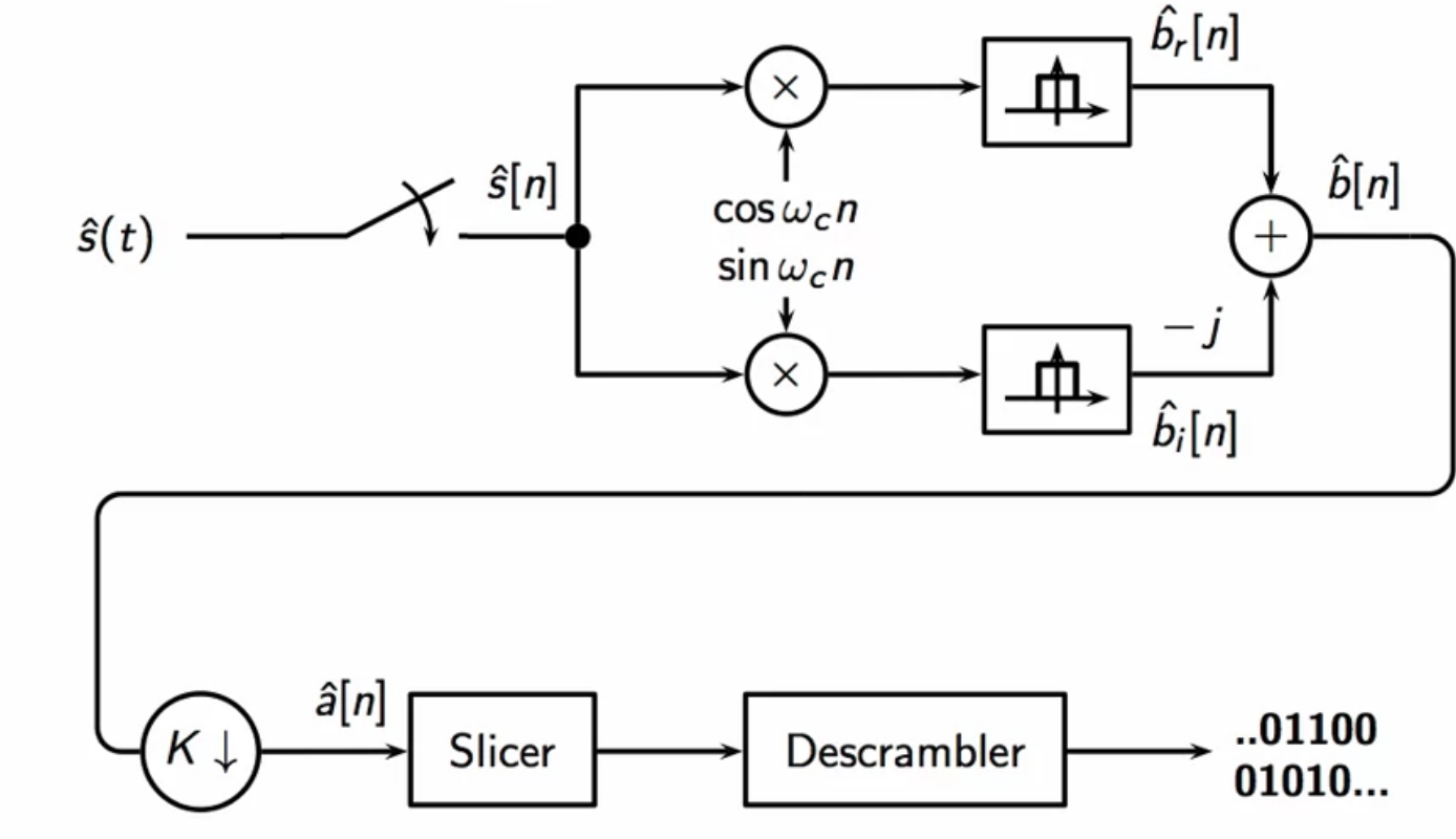
fig: QAM receiver signal flow schematic
voiceband modem application
channel specifications
- analog telephone channel
- \(F_{min} = 450 Hz; F_{max} = 2850 Hz \)
- usable bandwidth: \( W = 2400 Hz \)
- center frequency: \( F_c = 1650 Hz \)
- pick \( F_s = 3 * 2400 = 7200 Hz \)
- so K = 3
- \(\omega_c = 0.458 \pi \)
bandwidth constraint
- sampling theorem states that the sampling frequency is to be higher than twice the maximum frequency
- so atleast \( F_{max} * 2 = 2850 Hz = 5700 Hz \)
- upsampling also has to be considered, so sampling frequency must also be an integer multiple of the channel bandwidth
- channel bandwidth \(W = 2850 - 450 = 2400 Hz \)
- with center frequency \(F_c = 1650 Hz \)
- if upsamling factor is chosen to be three, then \( K = 3\)
- so sampling frequency \(F_s = 3 * W = 23 * 2400 = 7200 Hz \)
- this satisfies the sampling theorem frequency criteria as well
- in the digital domain, \( \omega_c = 0.458 \pi \)
- this is the modulating frequency
power constraint
- maximum SNR: \( 22 dB \)
- pick \( P_{err} = 10^{-6} \)
- using QAM, find M (number of bits per signal) \[ M = \log_2 \Bigg( 1 - \frac{3}{2} \frac{10^{\frac{22}{10}}}{ln(10^{-6})} \Bigg) \approx 4.1865 \]
- so pick M = 4 and use 16-point constellation
- 4 points in each quadrant
- final data-rate is \( WM = 4 * 2400 Hz = 9600 \) bits per second
- W: baud rate (bandwidth of the channel)
theoretical channel capacity
-
capacity formula based on signal bandwidth and SNR \[ C = W \log_2 (1 + SNR) \]
- only gives upper bound on the amount of information that can be sent over the channel
-
doesn’t actually state how to build a communication system to meet this specification
- for the previously designed scheme
- \( C \approx 17500 \) bps
- this hits half the channel capacity
- the gap can be narrowed with encoding techniques
- this topic needs a more thorough study of information theory